Intro
So its been nearly a month since I last put a blog post up and I have been working on some stuff in my free time between work (been traveling to the US and took a weekend off to visit some friends in Canada). I’m not particularly in the mood to write a new post, but you know how it is, if I don’t start writing it I’ll never get round to it.
Essentially I have always been fascinated by the idea of being able to ‘hack’ with/into physical things, whether it be the Arduino and my watering system (btw you can see those stats at http://andrewmohawk.dyndns.org/AWS/), changing data on RFID cards or being that sneaky kid jackpotting ATM machines.
I started looking at magnetic stripes, mostly because they are *everywhere*, from bank cards, customer loyalty and even parking systems.
Overview
The basic gist of the system is that there are many tiny magnets or magnetic particles (usually iron oxide) which are magnetized in a specific manner within a magstripe. Essentially you take the card (or think of it as many magnets) and put it next to a magnetic reader (card reader) which then reads the fields. These fields are then taken to good ol 1’s and 0’s and used within backend systems after a bit of decoding.
The magnetic stripe on a card is actually made up of 3 different ‘stripes’ or tracks (usually – different types of cards will have a different number of tracks), right above each other. Each of these tracks can hold different amounts of data and for the basic breakdown you can read up about em at http://www.gae.ucm.es/~padilla/extrawork/tracks.html and http://www.ded.co.uk/magnetic-stripe-card-standards/
TL;DR – Track 2/3 = Numbers, Track1 = UPPERCASE,numbers
Reading
Most magstripes use whats known as F2F/Aiken Biphase/BMC encoding, which determines whether something is a 1 or a 0 by looking at the change within a particular ‘phase’ (the time taken for one cycle). The time for a phase is identified by a series of 0’s at the beginning of each track (essentially just allowing the reader to say okay i see them coming past at x ms). This is known as self-clocking and allows readers to read cards that are pushed through by a human rather than say that of a tape player where it is a fixed speed.
This blog post very nicely describes how the reading works: http://www.qualifilms.com/blog/computer-science/2009/06/back-to-basics-reverse-engineering-of-a-non-standard-magstripe-part-one/ with images too!
TL;DR It works it out from the changes in the phase and does the timing from the initial 0’s
This diagram explains it best:

Reading a Magnetic Stripe
Building a Reader
So first things first, I needed to be able to successfully *read* magnetic stripes as an audio file so that I could start playing with them. The easiest way to do this was simply to create a magnetic stripe ‘reader’, there are a few posts on this and they basically come in the form of two options:
- Buy one (you can simply purchase a reader practically anywhere and then take it apart to get straight audio out – rather than the decoded wav
- Build one (this tech was used all over tape players way back so you can strip em to make one)
Because of my limited (read no) budget, I decided to build one from an old tape player.
Taking apart a Tape player
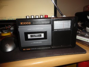
Initially I started by going to many different second hand stores, thrift shops and so on to look for a radio with tape player to use for this. Surprisingly people seem to have just thrown most of them away and I couldn’t find *any* near where I stay. However I have read about other people who have found plenty at second hand stores/tips etc. So look around. I found a really cheap one for R80 at a cheap chinese store near me:
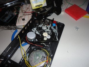
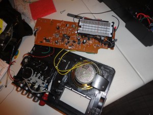
Anyway, I skillfully (read unskillfully) began disassembling (read destroying) my R80 tape player to get to the read head:
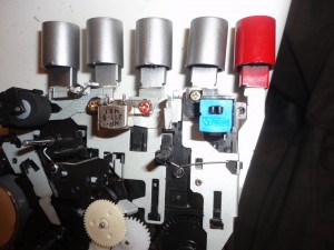
So after I had carefully (read completely uncarefully, possibly drunk and with all sorts of arb hammering/pulling and breaking) taken apart the packaging I could get to the juicy bits, the actual tape reading mechanism and specifically what I was looking for – the read head:
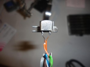
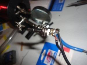
Next was the process of wiring up the read head (in silver) to the pc. Essentially the one side you need a mono jack (or take a stereo jack and wire a single wire to both sides of it – like i did) which will go into the PC to record the audio. These jacks can be taken from any old set of headphones or you can go and buy one at an electronics store (super cheap). The other side of the cable is simply wired to either side of the magnetic read head as below:
Reading cards:
The next stage after setting up the read head to a mono jack is to read the magnetic data on a card. As said before the ‘tracks’ are actually all on top of each other for generic cards. This page gives you a lot of really good information on the layout of cards and definitely recommended reading.
TL;DR: tracks are as follows:
| 0.223″ | TRACK | Recording Density (Bits per inch) |
Character Configuration (including parity bit) |
Information Content (inclusing control characters) |
| 0.110″ | 1 IATA | 210 | 7 bits per character | 79 alphanumeric charcters |
| 0.110″ | 2 ABA | 210 | 5 bits per character | 40 numeric characters |
| 0.110″ | 3 THRIFT | 210 | 5 bits per character | 107 numeric characters |
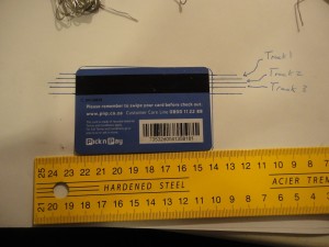
Essentially this means that if you wish to get the track information off you need to use a ruler to get the distance from the card correct and slide the magnetic read head along the edge of the ruler. This is a painful process as the ruler often moves or you are just above or below the track.
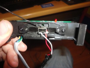
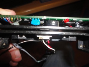
The way I have found to get it to work the best, is to simply find a second hand/broken/cheap TTL/other reader and modify it to have the magnetic read head go straight into the pc, something like this:
Working with Audio
Now you have a the reader setup, or a painful ruler setup the next step is to get the audio out. Fire up any old sound recorder (I like audacity), connect the Mono plug into the mic jack, hit record and swipe away!
I put up a sample of a generic customer loyality card at soundcloud: http://soundcloud.com/andrew-3/card-swipe/s-MvlVg
Within audacity you can see it as:
Zooming in to the card swipe you can see the data a lot clearer:
(the data above is the ‘clocking’ zeros followed by the first bits of the card)
How the audio works
The ‘audio’ is really just the encoded data, essentially a number of zero’s are seen at the front of the track so that the readers can determine the speed at which the card is moving through and ultimately the time it takes for 1 complete cycle. After it has got this ‘synched’ it will then start determining 1’s and 0’s by looking at whether the wave has changed within the specific period. This is also called Differential Manchester Encode / Bimark Phase Code / Aiken Biphase or F2F.
Its almost definitely best explained in images, and these great ones have been stolen from This blog:

Aiken Biphase

Aiken Biphase
As you can see above in the first two periods the wave has changed (the period is highlighted in red) and is subsequently a 1 where as in the 3rd and 5th phase it has remained the same (not specific to a high or a low) and is a 0.
Decoding the Audio
Major Malfunction has a great selection of python tools over at alcrypto.co.uk ( you’ll need to find the links), one of these being dab.py (Decode Aiken Biphase) – this script takes all the hard work (described previously) in getting the binary data out:
Decoding the Binary
So the binary is in the format of a 5 bit character (4 bits for the data and 1 bit for odd-parity checking) and works something like this:
Binary data: 11001
First four for data: 1100
Odd-Parity bit: 1
Looking at the above its first important to know that the parity bit (the last 1) is calculated by making sure there are an odd number of 1’s in the five bit sequence.
Next you can look at the ‘data’ which is 1100. The data is encoded with the least significant bit first, so the in essence it is read backwards and the actual data is 0011. This data can then be taken to decimal (0111 = 3), it is then shifted up 48 characters in the ASCII character set to return the ASCII value, thus the decimal value is 51 which is a 3.
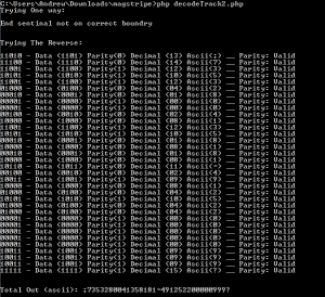
I whipped up a PHP script to do this for the data I got out previously which returns as follows:
As you can see in the above screenshot this decodes nicely to “;7353280041358181=491252200000999?” and the first part of that being the number printed on my loyalty card:
Code
The code is available on pastebin for those interested: http://pastebin.com/h9eVqRxz
<!--?php // AndrewMohawk // andrew@andrewmohawk.com // http://www.andrewmohawk.com /* Decode Track 2/3 data from binary */ $binary = "<yourBinaryHere-->"; // this function by mtroy dot student at gmail dot com taken from http://php.net/manual/en/function.strpos.php function strpos_r($haystack, $needle) { if(strlen($needle) > strlen($haystack)) trigger_error(sprintf("%s: length of argument 2 must be <= argument 1", __FUNCTION__), E_USER_WARNING); $seeks = array(); while($seek = strrpos($haystack, $needle)) { array_push($seeks, $seek); $haystack = substr($haystack, 0, $seek); } return $seeks; } function processBinary($binary) { $AsciiOutput = ""; //find start sentinal $start_sentinal = strpos($binary,"11010"); if($start_sentinal === false) { echo "Could not find start sentinal\n"; return false; } //find end sentinal $end_sentinal = false; $end_sentinals = strpos_r($binary,"11111"); if(count($end_sentinals) == 0) { echo "Could not find end sentinal\n"; return false; } //Check end sentinal is on a 5 bit boundry foreach($end_sentinals as $es) { $es = $es; if(($es - $start_sentinal) % 5 == 0) { $end_sentinal = $es; } } if($end_sentinal == false) { echo "End sentinal not on correct boundry\n"; return false; } //Lets decode the data: $bit_length = 5; // 4 bits for data, 1 bit for odd-parity or LRC checking $data = substr($binary,$start_sentinal,($end_sentinal-$start_sentinal+5)); $currentBits = ""; $currentNum = 0; $finalString = ""; for($i=0;$i<strlen($data);$i++) {="" if(strlen($currentbits)="" <="" $bit_length)="" $currentbits="" .="$data[$i];" }="" $paritybit="$currentBits[4];" $databits="substr($currentBits,0,4);" $asciichar="0;" for($x="0;$x<4;$x++)" $currentnum="" +="$dataBits[$x];" $dec="bindec($dataBits);" 2,="" "0",="" str_pad_left);="" just="" so="" output="" is="" nice="" reverse="" the="" binary="" (since="" its="" lsb="" first)="" then="" convert="" to="" dec,="" add="" 48="" and="" take="" it="" ascii="" echo="" "$currentbits="" -="" data="" ($databits)="" parity($paritybit)="" decimal="" ($dec)="" ascii($asciichar)";="" if(($currentnum="" $paritybit)="" %="" 2="=" false)="" "="" __="" parity:="" invalid";="" else="" valid";="" $asciioutput="" "\n";="" ;="" "\n\ntotal="" out="" (ascii):="" $asciioutput\n";="" "trying="" one="" way:\n\n";="" if="" (processbinary($binary)="=" reverse.="" "\n\n";="" reverse:\n\n";="" processbinary(strrev($binary));="" pre=""> |
Going Onwards:
So understanding the basics of how magnetic stripes work and how the data is encoded means that should I come into contact with other formats I know what to look for and can mess with them. Also knowing the above means I can write something to encode the data, generate wav files and build a spoofer to replay the attack :)
I’ll write a follow up sometime with spoofing magnetic stripes, here is a short video of me playing audio (since thats what it really is right?) from a spoofer to my magnetic read head:



[…] in the first blog post I discussed the basics of Magnetic stripes and how the tech works. I like it because its […]
Hi Andrew,
How do these magnetic strips decode the total amount or sale amount (most likely post tax)? Is it usually on the 1st or 2nd strip? How does it work? Or does the credit card terminal simply know how much each transaction is when authorizing card and amount through bank, credit card provider, etc.?
If the total after tax is recognized in the magnetic strip, which set of data is it usually? Is it usually under discretionary data?
Please respond to my email. And great website!
Best,
Matt
Hi Matt,
Magnetic stripes don’t hold any of the sale data at all, they merely hold the customer information, when you make a transaction the terminal speaks to the bank to approve/deny and you get the item.
-AM
How do I access these files alcrypto.co.uk help me pls thanks expression and php
Sorry, this I cant help with :(
Can you give me programs thanks
Hi, I’m working on a project like this but I found some issues in the recording stage. I had to build a small 3V preamp to get something usefull on my computer.
How did you get the signal from the read head directly to the computer? Does your sound card handle the preamplification? if it does what sound card are you using?
Regards.
Hi,
I presume its actually just the quality of the read head, I had some that I would have had to amp up the signal. I don’t think my sound card does any pre-amplification (but it could), just using the standard mic in jack and a relatively short lead directly from the read head->pc. However if you are just looking to get the data why not buy one of the cheap USB ones — they are super easy to use and just install as an HID device and ‘type’ whatever is read.
-AM