I realise I should have done this entry a little sooner, but as everyone should be well aware of by now, I am lazy. Also I moved to Cape Town just after ZaCon V which proved rather time consuming! Please note this is gonna be a first of 2 big entries on them so if you don’t like reading, pull up now.
Overview
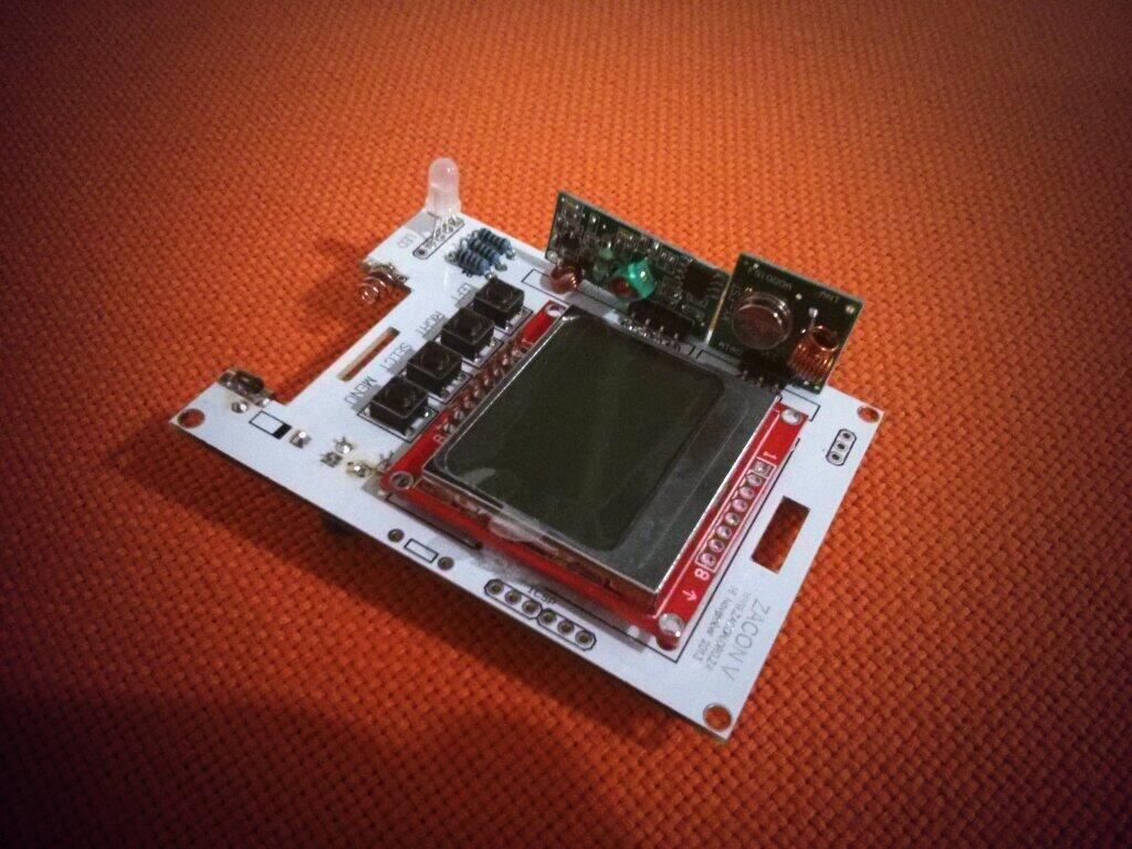
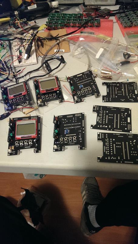
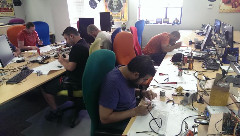
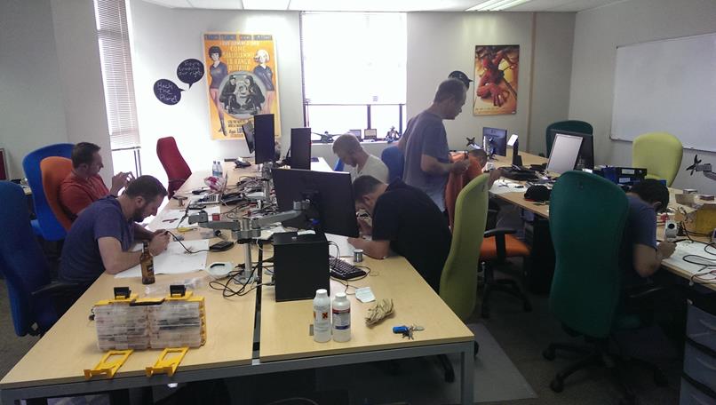
(pic from https://twitter.com/DavidBisschoff/status/401460570911956993/photo/1)
One of the highlights of the annual Las Vegas pilgrimage for me has always been the electronic badges, whether it’s for defcon, ninja networks or custom badges that people have built for their hackerspaces. I especially enjoy the ones that are a little more complex (more than just lights) and are hackable. I have always been in awe of security researchers such as Adam Laurie, Zak Franken, Michael Ossman, At1as and the other hardware hackers.
For ZaCon V ( www.zacon.org.za ) I built some electronic badges for the conference that are based on an Arduino framework (at least using an ATMega328 with an Arduino Bootloader) and communicate to each other via 433Mhz RF (the same that is used in remotes). The idea with the badges was to have a way to see who was interacting with whom and show it in a visual representation (Maltego — yes yes, man with a hammer etc). Additionally I needed the badges to be cheap as.. well… I am cheap :)
The badges took about 3 months to go from breadboard to finished and a large majority of that time was spent learning how electronics work (and don’t!). This however was not my first attempt at building badges, for the last 3 years I have built a design on a breadboard and then basically done nothing with it (apart from make a shakey cam video at 3am and suggest the idea).
A lot of the design actually came from me wondering around hobbyist electronic stores on the internet and coming across two really cool things namely, very cheap communication in the form of 433mhz RF chips and Nokia 5110 LCDs (also cheap :P ).
I ordered a few of the screens and RF kits and started tinkering- having a display connected to my Arduino brought all kinds of warm and fuzzy feelings. Next I started playing with the 433Mhz, originally thinking that the badges would only receive a simple message, something like who was currently speaking, from a PC near the stage. Roelof looked at it and suggested that this idea was boring and if I really wanted to do something cool I should make all the badges talk to each other. And so the tinkering began.
What I wanted to achieve
For me there are a few things that I really wanted the badges to have:
* Badges should communicate to each other, interactive badges are always going to be more fun
* A functional use for people who didnt want to ‘hack’ anything (ie schedule)
* Badges that can be ‘hacked’ or customized by both people who have played with hardware and people who have not
* Badges to be relatively cheap (I think in the end they were ~R100 [ $10 ] each)
Building
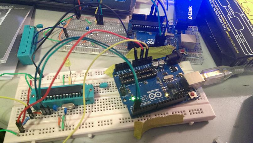
Originally my “badges” were a breadboard filled with an atmega328,9V battery (this is important for later), RF chips, buttons, a 5110 LCD and a bunch of wires:
This was great as it was the first time I had really ‘moved away’ from an Arduino and built something self standing (ish) — and it was really easy [http://arduino.cc/en/Main/Standalone]. With the RF I had a bit of background on from previously playing with my RTLSDR and RFCat to spoof remotes [ http://andrewmohawk.com/2012/09/06/hacking-fixed-key-remotes/ ] , so the debugging and getting something working was relatively quickly.
Then I started looking at how much components cost, and what I would need, turns out that pricing is relative when scaling up! This was especially clear to me as I was going to try and pay for these myself (ZaCon is a free community run conference that is strictly without sponsorship!). It was pretty hopeless and I was near ready to give up, but I decided to at least try make a couple of badges. Jameel (@RC1140) also got involved and pushed a lot to get stuff made and really motivated me to keep going.
So at this stage I needed a PCB, breadboards simply wouldn’t cut it. I google’d and came across a number of free PCB design suits that seemed relatively well used and figured “how hard can this be”. Protip: its not something you pick up in an afternoon. I decided to rather phone a friend who was an electronic engineer and get him to take a look at what I wanted to do. I popped round to his office for a few mornings and a PCB was born from the mangle of wires that made up the breadboard design. With that I ran skipping with a PCB design under my arm determined to get my first boards made. Special shouts to Mostert for doing this — without him id have never even got the first boards off the ground.
PCB production is also not that cheap (at least I anticipated it being cheaper), this was a rather big problem as I wasnt even sure that the designs would work. Luckily some kind friends of mine had a C&C machine and offered to mill a PCB for us. The one thing they did say to me before hand was that if it was 2 layer design (circuit on both sides of the PCB) they couldn’t do what is known as plated through hole (PTH), which essentially is just linking one side of the PCB to the other and is rather essential in design. “Thats fine” I said, thinking it wouldn’t be a problem. To put it into perspective PTH is worth more than bitcoin – not having it makes soldering components painfully tricky.
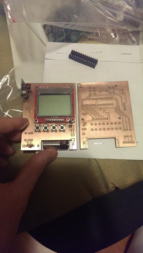
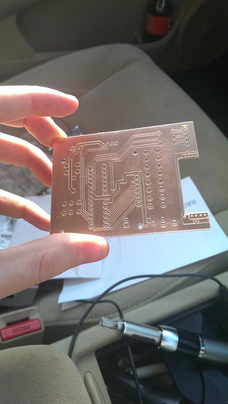
I got 3 copper c&c milled boards and Jameel and myself set off building the first badges. About half way through the first of mine the smell of plastic as overpowering and not having PTH was making my life a miserable train wreck. Jameel however managed to get some of the components I couldn’t get working going on his and re-motivated me to give it another go. Sure enough, the first time the board booted up, there was all kinds of shouting, leaping and skipping happened around my house.
After some careful examination of the design (ie, looking at it) I noticed that the RF chips where the wrong way round. Doh. Additionally the buttons were all tied to a few pins so I could save space originally, but this meant extra resistors and made the board messy. I needed a new board design anyway and went back to Mostert with my hat in my hand to request changes. I got the ICSP headers out, the buttons each got their own pin (overkill perhaps, but I had the pins) and I took out the extra pins that I wasnt using (these actually proved fairly useful as some of these were the RX and TX for Serial!
At this stage I decided that I could make at least a handful of badges for the organisers,Jameel and myself. I figured I could at least afford the components for a few boards and to get PCBs properly made.
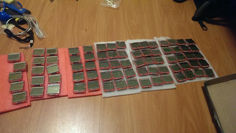
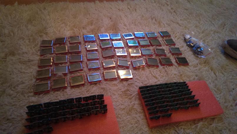
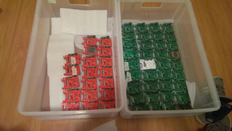
First up I needed to get the components, sourcing them locally (within South Africa) proved nearly futile as the components where a lot more expensive (especially when you look at doing a few). I dug a bit more around the barrows of the Internet and after listening to Adam Laurie and Zak Frankens talk at Defcon this year (2013) decided that eBay might not be a bad source to look for. Oh man was that one of the greatest days on the Internet I have ever had, between eBay and Alibaba I found absolute bargains for 5110 screens as well as the RF RX and TX modules. Unfortunately I had to purchase in bulk (25+) but the cost of these bulk purchases was still a lot cheaper than just purchasing a handful from local sources!
With a DHL tracking number I anxiously awaited the arrival of the components so that I could test these were the real deal prior to getting boards properly printed. Getting packaged electronics has also got to be one of the greatest things ever in that the packaging itself for them is absolutely exciting – I got more foam than at a kids party and things like anti-static tubes, all kinds of wonders I simply didn’t know about before!

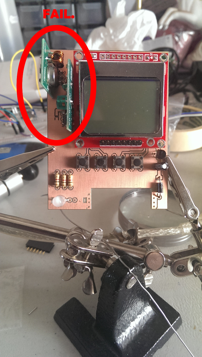
Not everything was great with my order however and it turned out that the components were slightly different to the original ones I had been using on the breadboards and CnC milled boards. The differences were subtle, but enough that I thanked my lucky stars I hadnt printed PCBs! The RF kits were slightly different in size and needed a little bit more spacing and the 5110 LCD displays had COMPLETLY different pin layouts! A few quick modifications to the design and I started getting quotations for real PCBs — the project was growing up. At the end I went with a place called Hackvana, their pricing was pretty decent and the support was near magical. They have an IRC channel where people give comments like “Andrew, seriously, diode on the positive terminal in case someone puts the battery in the wrong way round”. Generally really friendly, even from the hackvana staff, sending back comments and asking if I wanted to change things as they had some ideas they thought could improve the design.
The only issue I did encounter with using international suppliers (of both the PCBs and the RF+LCD kits) was the random custom tax that I got on each order which meant I simply couldn’t budget properly for anything. For the first LCD+RF kits I got I was charged 0% customs (wo0t!), my first PCB run earned me a measly 12%, the second component run got me 15% and the third ended up being 18%. As such I didn’t order anything from the internet for the remainder of the month for fear of it costing me 18% in customs!

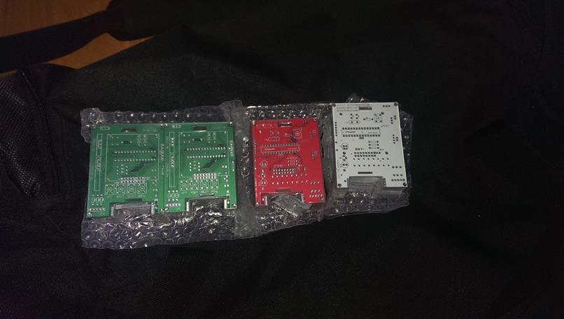
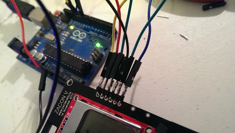
With my new PCB designs and components I sent off the first order I had ever placed for a PCB. They arrived, black and shiney and gave me a tingly sensation in parts of my body I didnt think could tingle. I instantly began soldering a few of them together and created a quick video of them “communicating”:
There were a two minor problems with the boards, but as functionality goes, they were operational! The two problems were:
* Backlight was not shorting the correct pins, in fact using the pad would actually short the entire badge (see previous comments about engineering experience)
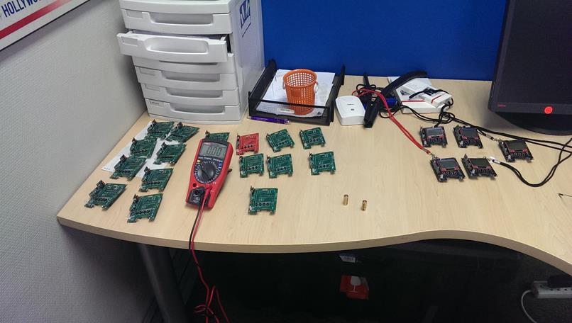
* A few of my eBay 5110 LCDs refused to work on the badges.
The first was a minor fix. The second however proved to be the most troublesome part of the entire building process. Firstly it is nigh impossible to cleanly remove the 8 pins connecting the LCD to the PCB with a soldering iron and my skillset. It ended up being easier to break the LCD rather than break the board during the removal process. The second problem was that I have no idea (And still do not) know why some of the LCDs failed. They worked flawlessly when connected to my Arduino on a broadboard, the voltages were the same between what the PCB was giving them and what the breadboard/Arduino was giving them, it still bothers me and if anyone has any ideas please let me know! To solve this problem I bruteforced it after a suggestion from Roelof (he personally spent a long time trying to fix this! ruzpekt). I sacrificed a PCB to attach Pin Headers to it to manually test every screen before soldering it on. The success rate was around 70%, which meant that I was essentially losing 3 screens out of every 10!
Additionally I also changed the PCB design to include the pins for what I now refer to as the “sparkfun” LCDs with the standard pin out so that if someone wanted they could use either of them (and in case we ran out of screens I could actually buy locally to get working components).
I made the changes and got the final PCB designs, now I just needed to get some money to print em! As this was the very first time ZaCon (and perhaps any .za security conference) had electronic badges, I really wanted to keep it a secret until just before the conference. This however meant that asking people for donations would be out of the question as it would give away that we had badges! I spoke to people@ (Organisers of ZaCon) and asked if there was any way I could get sponsorship and that I needed a fair amount of money. Naturally sponsorship was out of the question but Haroon Meer and Dominic White both offered substantial donations on behalf of their organisations to get the badges printed.
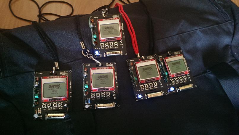
With this I skipped, clicked and whistled all the way to the PCB printing and component ordering. We decided to just do 80 additional badges – 40 for attendees, 20 for speakers and 20 for “DIY” (people who would build at the ZaCon Nights event the night before). The components and PCBs all arrived about 2 weeks before the conference. Suddenly time was against us as it takes about an hour to solder everything together the first time, 25 minutes if you have done a few of them and about 18 minutes if you have “skillz that killz”. This meant that even at the fastest doing 60 badges would take you 1500 minutes / 25 hours. With just two weeks to go and a day job, neither myself nor Jameel had time for it! Panic naturally set in as quickly as pressing up on a SQL commit and seeing you didn’t include a WHERE clause.
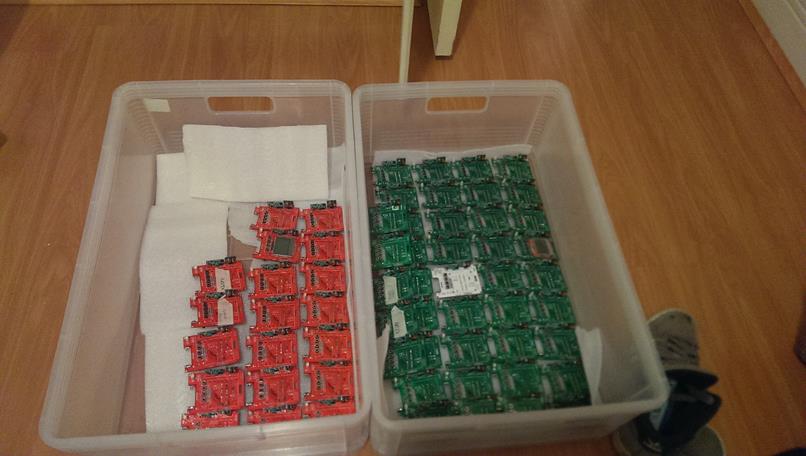
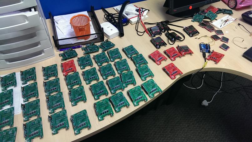
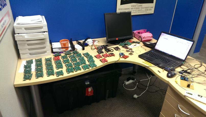
Luckily, we managed to organise a ninja stealth team of helpers who all gladly gave up a Saturday (our only weekend before the event) to solder badges. Special thanks to Dominic, Keiran, George, Ettiene, Roelof, Todor and Jameel who pulled off doing all 60 badges (without screens as these were still a problem). Some of the guys had never soldered before, but due to their leet skillz they managed to pick it up rather quickly and definitely deserve some sort of soldering achievement award!
At this stage all the badges where made, it merely took flashing the chips, testing and we were good to go, it took many sleepless nights but I am impressed they came out so well!
Failures:
I had never had one of my “breadboard badges” run out of juice using my 9v Battery. This is because it is a 550mAh battery, battery life barely crossed my mind during the development stage. I got a few complaints when asking people about carrying a 9V battery as it was very bulky. Mostert suggested I use a 23A battery (smaller, mostly used in gate/garage/car remotes), I thought “great”, its a 12V battery, its got to be better than my 9v right. Since you know.. 12 is greater than 9.. As you may have guessed, I havent worked very much with batteries nor do I have an engineering background. So what you really want to look for in batteries is the mAh to tell you how many amps they can provide. My previous batteries had a 550mah whilst the new ones that I thought were so lovely were 40-55 mAh.
Additionally I REALLY liked the RGB LED and didnt account at all for all the power usage on the board. As such this meant my boards were actually pulling 20-25mA and essentially worth about 1.5-3 hours of life depending on how much RF they were doing. I started by changing the LED to stop blinking every time something happened, and instead of the RF transmitting and receiving every few seconds it would only do this every Rand(1,30) seconds.
These problems naturally came after everything had been built during the testing phases, many tears where shed and at the end I bruteforced the problem by making sure I had 3 batteries for every badge so that they could at least keep them on for the duration of the con!
Hacking:
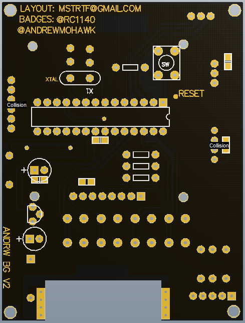

The final design as pictured above also included various pinouts for the ATMega chip which turned out to be a blessing in disguise. I figured it was nice so that people could merely extend the badges to do whatever they wanted and they had a handful of pins to play with. Lucky for us the pins that were external where for the ISCP which meant it was really easy to reflash a badge from another Arduino and RX,TX and RST for Serial communications which meant that people could even extend their badges to communicate over serial to almost anything.
The pinouts and code are linked to and described in the previous post -> http://andrewmohawk.com/2013/11/06/zacon-v-badge-sneak-peak/
Whilst the badges communicated via RF (and i’ll cover this in a seperate post describing how they work), there were a number of ways in which if the badges sent a ‘special’ code they could influence other badges, like making them “police car”, which meant the RGB LED flashed blue/red/white and the screen displayed the text ‘owned’. You could also send specific commands to save text to the badges EEPROM (so its there even after reflashing) and a few other bits and pieces within the code.
The best hack that happened on the day was that the RF kits specifically didn’t have antennas attached to them so that the badges could only communicate in <1m range which worked really well for what I was doing (showing relationships). A few of the guys from the cape town massive attached antennas to their badges with the correct length and ended up being “friends” with *everyone* at the conference and having their information pushed to the screen the most :)
Additionally a few of the guys also ended up police car`ing everyone which was relatively entertaining!
From my side the first thing I did was wire up the badges straight to USB so that I dont need to worry about the power issues and i’d definitely recommend doing that for anyone who wants to use the badges for any sort of haxz0ry later on :)
Thoughts

The badges worked surprisingly well for my first attempt and visualised in Maltego it was beautiful. The hackability also gives me the idea for 2 additional projects:
The good: In south africa we have a number of people who are stealing from cars by ‘jamming’ the signal when someone tries to lock their car and hope that they do not notice. With the badges you could easily modify them to try and pick up these signals and notify the user of the badge that it is going on and help people stop this sort of thing.
The bad: You could also modify the badges to do replay attacks where they could listen for a signal, save it and then retransmit it to open garages/gates or if you were able to capture say a car remote being pressed out side the range of the car you could use that to open it.
Hey Sergio, it’s getting kind of hot on here.
-Andrew
[…] ZaCon badges were a ton of work on the hardware side (see ZaCon V Badge [1/2]: Build Time), however they provided their own challenges on the software side as […]
[…] describing electronic conference badges that he built for a free South African security conference (part1, part2). The end platform shown above is based on an ATMega328, a Nokia 5110 LCD, a 433MHz AM/OOK […]
[…] describing electronic conference badges that he built for a free South African security conference (part1, part2). The end platform shown above is based on an ATMega328, a Nokia 5110 LCD, a 433MHz AM/OOK […]
[…] describing electronic conference badges that he built for a free South African security conference (part1, part2). The end platform shown above is based on an ATMega328, a Nokia 5110 LCD, a 433MHz AM/OOK […]
[…] describing electronic conference badges that he built for a free South African security conference (part1, part2). The end platform shown above is based on an ATMega328, a Nokia 5110 LCD, a 433MHz AM/OOK […]
[…] describing electronic conference badges that he built for a free South African security conference (part1, part2). The end platform shown above is based on an ATMega328, a Nokia 5110 LCD, a 433MHz AM/OOK […]
[…] describing electronic conference badges that he built for a free South African security conference (part1, part2). The end platform shown above is based on an ATMega328, a Nokia 5110 LCD, a 433MHz AM/OOK […]
[…] Andrew Nohawk recently attended ZaCon V, a free South African security conference. In honor of the event, Nohawk decided to design an interactive mesh networked conference badge. […]
I’m an amateur with very little clue what I’m doing, so, be gentle. I’ve also had problems with LCDs that appear not to work (16×2 Alphanumeric). The problem turned our to be the USB out of my netbook was only 4.5V, and this caused the contrast to be incorrectly set. Maybe check that your contrast pin voltage.
Interesting.. Actually I was powering these off various batteries to rule out that possibility, but i’ll definitely keep this in mind!
[…] and RF components. He provides a detailed chronicle of his design and development process in this post. He explains, “For ZaCon V I built some electronic badges for the conference that are based […]
[…] Andrew Nohawk recently attended ZaCon V, a free South African security conference. In honor of the event, Nohawk decided to design an interactive mesh networked conference badge. […]