The ZaCon badges were a ton of work on the hardware side (see ZaCon V Badge [1/2]: Build Time), however they provided their own challenges on the software side as well.
Since my knowledge of chipsets only extended to the Arduino the badges are essentially a complete Arduino without the UBS->FTDI breakout. This means that each badge includes an Arduino bootloader which is _really_ nice if you are coming from an Arduino background or simply have an Arduino and want to play.
The idea behind the badges was that they would provide a means of tracking communication between individuals at the conference. Additionally I wanted this information transmitted to a central location so that it could be stored and visualised (yes yes, Maltego and all). Additionally because people would be moving around I needed to create a ‘mesh network’ of sorts so that anytime someone came into range of any other badges they would be automatically be part of the network. This blog entry is going to cover how the badges did this and the challenges faced, if you are not interested make like a heartbleed and go away.
Eye Candy:
Here is a video of a few of the black badges communicating to each and flashing for all the valid messages received:
Interface:
The badges had 4 buttons to control them namely left,right, select and menu. The interface included the following sections:
1. Intro – 8 bit intro screen ( this is actually shown in part when booting the badges — its just a shorter version)
2. About – Simple text about the badges
3. Schedule – Schedule of the speakers and their timeslots with the ability to page through them
4. Live Speaker – Simply shows the current speaker (no paging)
5. WHOAMI – Screen that loads custom WHOAMI data that attendees could send to their badges via RF
6. Stats – Shows your badge number (for people trying to identify themselves on the live graph), number of badges seen and available memory
Having only 2K of RAM available meant I couldn’t go crazy with features (not that I really had the time anyway) and was particularly troublesome to debug. For example the badges would run out of memory if too many other badges were seen and of course looked to be behaving normally but were no longer transmitting or receiving. Using Serial to output debug data also ended up using too much memory and stopping the badges from working before they got to that stage (and provided many an hour of frustration until I figured out the way I was debugging was causing a problem!)
Here is a quick video of me running through the menu:
This is one of the test badges so its using a USB cable for power and has antennas on the RF chips and has a ‘log’ menu item. The normal badges looked much neater:
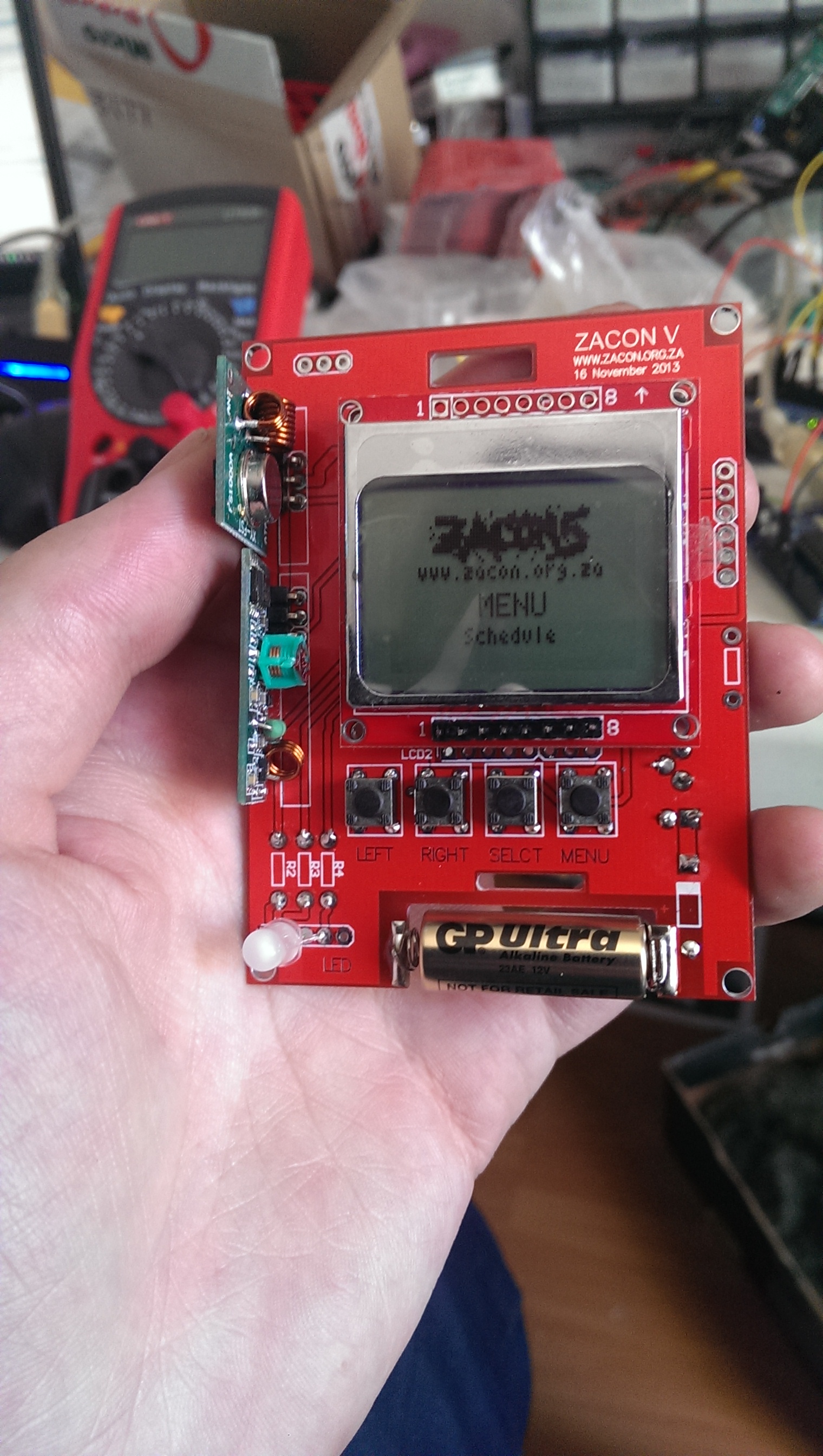
Speaker Badge 0001
Hackability:
As said before the badges all run Arduino bootloaders which means you could easily remove the chip, pop it into an Arduino UNO and reprogram it to do whatever you needed it to do. The layout also took the ICSP pins out so you could program it straight from another Arduino as well without having to remove the chip (the writeup for those is in sneak peek update). Additionally pins 0,1,2 (RST,TX,RX) were exposed (as well as ICSP pins) which meant that you could receive Serial output from the badges and integrate that with other devices (Arduinos, Pis, etc) that could use that data — There was someone trying to get their badge to tweet every time it encountered another badge!
The hackability I wont get into as such, you can read about it in the final thoughts of ZaCon V Badge [1/2]: Build Time andunder hackability at ZaCon V: Badge Sneak Peak *update*
Communication:
The badges were using some very cheap radio chips (see hardware writeup) which meant that all communications were done via 433Mhz AM/OOK. This is the same used in car/garage remotes and you can read my entry on hacking fixed key remotes discussing how to process this type of data and use it to your advantage (replay / spoofing).
The badges themselves worked with the following “protocol” (I realise this is too much, but I couldnt think of another word!):
* S<XXXX> – Badge transmitting or Sending its badge number, eg. S1337
* R<XXXX>:<YYYY> – Badge transmitting a Relationship between XXXX and YYYY, eg. R1337:1338
* A1985 – Resets badges back to ‘Factory’ (no relationships, no seen badges)
* L<XX>: Set current live speaker to XX (this reads from memory and shows it on screen without any checking)
* U<text>: Line one for WHOAMI data
* V<text>: Line two for WHOAMI data
* W<text>: Line three for WHOAMI data
* C<????>: ‘coolbadge’ mode where ???? is 1111,2222,3333,4444,55555 – more on this later
The badgenumbers themselves differentiated between the ‘class’ of badge where:
* 1000-1999: VIP/Black Badges
* 2000-2999: Build-your-own-badge Attendees (BYOB — not that kind :P )
* 3000-4000: Speakers
* 4000-5000: Pleb Attendee’s
Mesh Network
With the RF chips and they way that the virtualwire library integrates with the Arduino I could not transmit and receive at the same time. This proved a troublesome hurdle for what I was trying to do and this is what I decided for the ‘mesh network’
* Each badge will transmit its own badge number every Rand(1,30) seconds (this also saved some power!)
* When a badge isnt transmitting, it is ‘listening’ for any valid messages
* If a badge ‘hears’ another badge number (or a relationship – covered next) it will store that in the EEPROM (so even after restart/battery failures it knows its seen that badge)
* Additionally to transmitting its own badge number, badges will also store a relationship between two badges, this can either be its own (from the last 5 badges seen) or another relationship between two badges.
In ordered steps the relationship between 4 badges might be as follows:
1. Badge A transmits its badge number
2. Badge B ‘hears’ this and stores ‘A’ in its EEPROM as a badge seen
3. Badge A might move out of range now as the person moves somewhere else
4. Badge B now transmits its badge number as well as a relationship between A and B
5. Badge C ‘hears’ the above transmission, stores ‘B’ in EEPROM and the relationship between A and B in memory
6. Badge C now transmits its badge number as well as a relationship (either between C and B or between A and B — this is randomly picked)
7. Badge D hears the above and stores it as per step 5.
What this means is that even though badge D is not within range of A and B it knows about the relationship as it travelled along the ‘network’. Visually this looks as follows:

Badge ‘Protocol’ Example
Badge Setup
Doing various tests also proved rather troublesome as I had to isolate badges so that they could not ‘see’ each other. I tried using foiled chip packets which I had read on the Internet (which naturally never lies) would stop all kinds of RF communication, this is a lie, other lies include tinfoil and whatever else you read on the damn internet.. In the end I placed 2 of the badges in the microwave, let 2 sit on my desk and used a ‘middleman’ badge to move between them to determine if the two in the microwave would then know about the relationship between the two on the desk and have that stored. I coupled this with turning badges on and off at different times to simulating them moving in and out of the ‘network’.
One of the nice things about buying REALLY cheap RF chips was that their range without an antenna (by default) was APPAULING (even if the datasheet says 90 meters), which means they are horrid to use for a real RF project but perfect for mine. During testing the range of the RF was about 30->50cm, far enough that I could still measure when people were talking to each other but close enough that I dont get an entire room if people are sitting next to each other.
Server Setup
With setup of the badges done and code in place I then started working on the “server” side which was relatively simple. It came down to having a single Arduino that had a higher quality 433Mhz RX unit that would listen for any valid communication (see ‘protocol’ above) and then store that in a sqlite database. The Arduino was connected to a computer via USB and was spitting out the data in real time via serial. The computer simply opened the serial port and parsed that data into the database. The range was not that good (about 10-15 meters from the stage) but it meant that if there were people close enough to the front they would still have their badges tell the “server” that they were there (see ‘mesh network’ above). The data was stored in three main tables: raw_data, relationships and badges which consisted of the following:
* raw_data: ID, Seen, Data
ID – Row ID
Seen – Timestamp for when this data was seen
Data – actual message that was seen
sqlite> select * from raw_data limit 5;

2379|1384563726|S4099

2380|1384563726|R4099:1002

2381|1384563734|S4099

2382|1384563739|R4099:1002

2383|1384563740|S1001
* relationships: ID, Seen, BadgeNum1,BadgeNum2
ID – Row ID
Seen – Timestamp for when this relationship was seen
BadgeNum1 – First badge number in relationship
BadgeNum2 – Second badge number in relationship
sqlite> select * from relationships limit 5;

1511|1384563726|4099|1002

1513|1384563740|1002|4099

1514|1384563740|1001|1002

1523|1384563775|1002|1001

1527|1384563781|1335|1001
* badges: ID, Seen, BadgeNumber
ID – Row ID
Seen – Timestamp for when this badge was seen (unixtime)
BadgeNumber – Badge number
sqlite> select * from badges limit 5;

807|1384563726|4099

809|1384563740|1001

810|1384563743|1002

812|1384563751|1335

820|1384589019|4015
The second component was having the entire system work within Maltego so there would be a graph that would constantly be building as people were picked up and put in the database. This actually worked really well and only consisted of a two main components:
– Transforms
— Get Current Badges: This pulled all badges that were seen at the conference
— Get Relationships: This transform pulled all the relationships for a particular badge
– Machine
— ZaCon Machine: This simply ran on a ‘location’ entity and then pulled all the current badges and then all the relationships for each badge (as per the two above). This would then repeat the process every 30 seconds.

What this meant was that at the conference I had fatty (my old 17″ Laptop) running on stage plotting all the users as they interacted every 30 seconds. This can be seen above with a few badges during testing. The actual graph from https://github.com/AndrewMohawk/zaconv/tree/master/database_and_maltego_graph looks as follows:

ZaCon V Maltego Graph
Conclusion/Downloads / Thanks
Of the 77 badges soldered together (at various stages of ‘full working order’ – especially the BYOB people) the front computer captured 9810 transmissions, 49 badges and 201 different relationships. The numbers are a bit lower than what I was hoping for, only 63% of badges captured but are due to a few different reasons:
1. A number of people simply didn’t go near the front computer (which didn’t have enough range for the entire audience)
2. A number of badge transmissions may have been missed as the badges do not constantly send out their numbers nor their relationships and we required that to happen when they were in range of the front computer
3. A few people might have simply left from BYOB or got their badges and left (we will find you.)
4. Some of the badges might have either the TX or RX components faulty
You can pull the code, raw sqlite database, Maltego graphs from the github page: https://github.com/AndrewMohawk/zaconv . This is the first time I’ve ever used GitHub, special thanks to RC1440 who also contributed heavily to the project and for getting me to use it and finally stopping me from just randomly storing code :)
-AM
[…] electronic conference badges that he built for a free South African security conference (part1, part2). The end platform shown above is based on an ATMega328, a Nokia 5110 LCD, a 433MHz AM/OOK TX/RX […]
Do you have any extra PCB’s for purchase and a BOM that you can post? I would love to get my hands on one or two of these.
Where abouts are you? I may have some of the broken badges that just need 1 or 2 components replaced.